How to Test a Dual Run Capacitor: Microfarad Tolerances & Dielectric Safety
Testing a dual run capacitor requires isolating high voltage power, discharging electrical charge across insulated resistors, and measuring microfarad capacitance across the HERM, FAN, and Common terminals.
Capacitance readings falling more than six percent below nominal ratings indicate internal dielectric breakdown, requiring immediate component replacement to prevent locked rotor compressor failure.
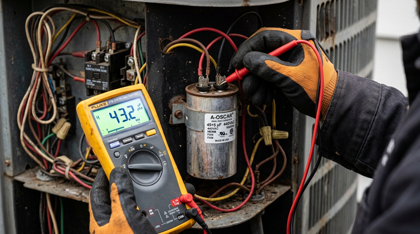
Diagnostic evaluation and precision measurement of heating and cooling components.
Electrical Isolation & Capacitor Safe Discharge Protocols
Dual run capacitors store lethal electrical potentials up to 440 volts alternating current even when main circuit breakers are turned off.
Field technicians must pull the outdoor disconnect handle, verify zero voltage with a calibrated non-contact tester, and discharge capacitor terminals across a 20,000-ohm 2-watt resistor before touching terminals.
Never short capacitor terminals directly with a bare metal screwdriver. Direct terminal arcing pits contact surfaces, risks explosive dielectric vapor venting, and damages delicate multimeter measurement circuitry permanently.
Always wear safety glasses and insulated 1000-volt gloves during physical electrical testing. High humidity and surface moisture on outdoor condenser units increase electrical flashover risks dramatically during summer storm seasons.
After bleeding off stored voltage through the discharge resistor, connect multimeter test leads set to DC volts across each terminal pair. Confirm that residual electrical potential drops below 1 volt before proceeding with physical wire disconnects.
Terminal Identification & Wiring Configuration (HERM, FAN, C)
Modern dual run capacitors house two separate internal capacitors inside a single hermetically sealed aluminum cylinder. Technicians identify three distinct terminal posts stamped on the top metal disc: Common (C), Hermetic Compressor (HERM), and Condenser Fan Motor (FAN).
The Common terminal typically features four male spade contact prongs. It receives the incoming line voltage feed directly from the T1 or T2 load side of the compressor contactor relay.
The HERM terminal typically provides three contact prongs. This terminal connects directly to the start winding of the high-torque scroll or reciprocating compressor motor.
The FAN terminal has one or two contact prongs. It routes phase-shifted electrical current to the auxiliary start winding of the outdoor condenser fan motor.
Tag each wire connection with electrical marking tape before detaching leads. Swapping the HERM and FAN wires causes immediate compressor stalling and damages the outdoor fan motor windings permanently.
Digital Multimeter Capacitance Testing Procedures
Accurate capacitor evaluation requires a digital multimeter equipped with dedicated microfarad capacitance measurement capabilities. Technicians disconnect all wires from capacitor terminals to isolate internal circuits from parasitic motor winding resistances before attaching instrument alligator test clips.
Rotate the multimeter selector dial to the capacitance setting designated by the microfarad symbol (µF). Ensure the multimeter battery maintains fresh voltage, as weak meter batteries produce artificially depressed capacitance readings.
Attach the common black test lead to the Common (C) terminal post. Touch the red test probe firmly to the HERM terminal post and allow the meter digital display to stabilize for five to ten seconds.
Record the displayed microfarad value on your service log sheet. Repeat the measurement procedure between Common and the FAN terminal post to evaluate the fan motor circuit independently.
If the multimeter displays OL or zero microfarads, the internal aluminum foil plates have suffered complete open-circuit separation, confirming total capacitor failure.
Microfarad Tolerance Limits & Manufacturer Replacement Rules
Industrial HVAC capacitor manufacturing standards governed by EIA-456 establish a strict plus or minus six percent operating tolerance. A dual run capacitor stamped 45/5 microfarads must deliver between 42.3 and 47.7 microfarads on the HERM circuit to maintain proper motor torque.
Operating a compressor on a weakened capacitor measuring more than six percent below nominal value causes motor windings to pull excessive running amperage. Increased current draw trips thermal overload switches and destroys synthetic winding insulation over prolonged cycles.
Review the operational tolerance benchmarks compiled below to determine whether your capacitor qualifies for continued field service or immediate emergency disposal.
| Capacitor Label Rating | Minimum Allowable HERM µF | Minimum Allowable FAN µF | Operating Verdict |
|---|---|---|---|
| 35 / 5 µF (±6%) | 32.9 µF | 4.7 µF | Replace below 32.9 µF |
| 40 / 5 µF (±6%) | 37.6 µF | 4.7 µF | Replace below 37.6 µF |
| 45 / 5 µF (±6%) | 42.3 µF | 4.7 µF | Replace below 42.3 µF |
| 50 / 7.5 µF (±6%) | 47.0 µF | 7.05 µF | Replace below 47.0 µF |
| 70 / 10 µF (±6%) | 65.8 µF | 9.4 µF | Replace below 65.8 µF |
Physical Symptoms of Imminent Dielectric Oil Breakdown
Visual inspection reveals capacitor failure when the top aluminum terminal membrane bulges upward, resembling a rounded dome. Bulging indicates severe internal thermal over-pressurization and dielectric oil breakdown caused by excessive ambient heat, prolonged run cycles, or voltage transients.
Modern capacitors incorporate internal pressure-sensitive interrupters designed to disconnect foil plates mechanically when internal gases expand. A bulged top lid confirms that this internal safety mechanism has activated permanently.
Look for oily liquid residue pooling around the terminal posts or dripping down into the bottom of the electrical control cabinet. Leaking dielectric oil eliminates insulating resistance between foil layers, leading to rapid internal short circuits.
Listen for audible humming noises originating from the outdoor condenser while the fan blade sits motionless. A stalled compressor drawing locked rotor amperage creates rhythmic 60-cycle electrical hums that demand immediate equipment shutdown.
Selecting Certified 370V vs 440V Replacement Components
Replacement capacitors must match the exact microfarad specifications stamped on the original equipment manufacturer label. While capacitance ratings cannot be altered, technicians recommend upgrading from 370-volt to 440-volt rated capacitors to provide superior dielectric insulation thickness against summer voltage spikes.
A 440-volt capacitor operates comfortably in a 370-volt circuit because voltage ratings indicate maximum dielectric tolerance rather than supplied operating voltage. The thicker internal dielectric film dissipates ambient heat more efficiently during prolonged triple-digit summer heatwaves.
Never install a capacitor with a voltage rating lower than the original specification. Installing a 370-volt replacement in a system engineered for 440 volts causes accelerated dielectric puncture and catastrophic premature component failure.
Always secure replacement capacitors firmly inside the cabinet mounting bracket. Loose vibration damages aluminum casing walls and creates electrical ground faults against neighboring sheet metal panels.
Frequently Asked Questions About How to Test a Dual Run Capacitor
Review common diagnostic questions and field answers regarding How to Test a Dual Run Capacitor. Consult certified HVAC professionals when performing electrical or thermodynamic testing on residential and commercial cooling equipment.
Can a Bad Capacitor Damage the Compressor Motor Windings?
Operating an air conditioner with a degraded capacitor forces the compressor motor to draw locked rotor amperage continuously, generating extreme internal heat that destroys synthetic enamel winding insulation.
Prolonged operation under depleted capacitance causes catastrophic motor burnout, requiring costly complete compressor or condensing unit replacement.
Can I Replace a 370 Volt Capacitor with a 440 Volt Model?
Technicians frequently upgrade 370-volt capacitors to 440-volt models because higher voltage ratings provide thicker dielectric insulation, superior surge tolerance, and longer service life under high ambient temperatures. The replacement capacitor must match the original microfarad rating exactly to maintain balanced motor phase displacement.
What Causes Dual Run Capacitors to Fail in Summer Heat?
Excessive ambient summer temperatures exceeding 100 degrees Fahrenheit, high operating run times, and localized utility voltage spikes accelerate dielectric fluid breakdown inside aluminum capacitor casings. Dirty condenser coils compound thermal stress by increasing compressor head pressures and electrical current draw beyond rated engineering thresholds.
Need an Emergency HVAC Technician On-Site?
Our licensed 24/7 emergency technician dispatch network arrives in mobile service vans within 15 to 30 minutes, carrying factory-authorized universal parts to restore heating and cooling on the first visit.