R-410A Subcooling vs Superheat: HVAC Refrigerant Charging & TXV Diagnostics
Accurate HVAC refrigerant charging requires calculating liquid subcooling on systems equipped with thermal expansion valves or suction superheat on fixed orifice piston systems.
Comparing subcooling and superheat simultaneously allows technicians to differentiate between low refrigerant charge, restricted metering valves, and improper indoor airflow without guessing.
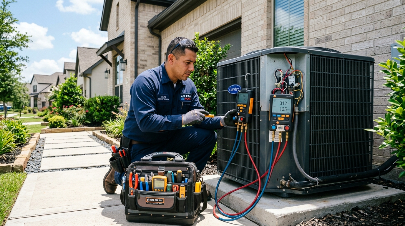
Diagnostic evaluation and precision measurement of heating and cooling components.
Thermodynamic Liquid Subcooling Calculation Principles
Liquid subcooling measures the temperature drop of liquid refrigerant below its saturation condensing temperature at high-side discharge pressure. Technicians measure liquid line pressure with digital manifold gauges, convert PSI to saturation temperature using a PT chart, and subtract the physical copper pipe temperature.
Target subcooling ratings stamped on manufacturer unit data plates typically range between 10 and 14 degrees Fahrenheit. Low subcooling below 5 degrees indicates refrigerant undercharge, whereas high subcooling above 18 degrees signifies a restricted thermal expansion valve.
Subcooling ensures that pure liquid refrigerant reaches the thermal expansion valve inlet without flash gas bubbles. Vapor bubbles entering the metering port cause erratic hunting, reduced cooling capacity, and audible hissing noises.
Always measure liquid line temperature within six inches of the service valve using an insulated thermistor clamp. Uninsulated temperature sensors exposed to hot outdoor ambient airflow produce false high temperature readings that skew subcooling calculations.
Suction Superheat Verification Across Evaporator Coils
Suction superheat measures the sensible heat gained by vapor refrigerant after complete boiling inside the evaporator coil. Measuring suction line temperature and subtracting low-side saturation temperature ensures that zero liquid refrigerant droplets return to destroy the compressor scroll plates.
Normal operational superheat ranges between 8 and 14 degrees Fahrenheit at the indoor air handler outlet. High superheat combined with normal or high subcooling confirms a starved evaporator caused by a stuck TXV power element.
Compressors are vapor pumps designed strictly to compress gaseous refrigerant. Low superheat below 4 degrees risks liquid refrigerant floodback, which washes lubricating oil off compressor bearings and causes mechanical seizure.
On fixed orifice systems, technicians consult indoor wet-bulb and outdoor dry-bulb target charts to determine optimal superheat. Fixed piston systems cannot adjust refrigerant flow dynamically to changing heat loads like modulating TXVs.
Four-Quadrant Diagnostic Matrix: Differentiating System Faults
Comparing subcooling and superheat concurrently enables technicians to diagnose complex mechanical and airflow anomalies with definitive mathematical certainty. Evaluating either metric in isolation leads to improper refrigerant additions that exacerbate compressor stress.
Review the diagnostic relationship matrix below to identify whether your cooling system suffers from a refrigerant leak, an overcharge condition, a restricted metering valve, or restricted indoor airflow.
Notice that low suction pressure can indicate either low refrigerant charge or restricted airflow. Examining liquid subcooling provides the missing diagnostic link that eliminates trial-and-error refrigerant additions.
| Operating Condition | Liquid Subcooling | Suction Superheat | Root Cause & Field Remedy |
|---|---|---|---|
| Refrigerant Undercharge | LOW (< 5°F) | HIGH (> 18°F) | Refrigerant leak. Locate leak, braze, pull vacuum, weigh charge. |
| Refrigerant Overcharge | HIGH (> 16°F) | LOW (< 6°F) | Excess refrigerant. Recover refrigerant to factory nameplate specs. |
| Restricted Metering Device (TXV) | HIGH (> 18°F) | HIGH (> 22°F) | Stuck TXV power element or moisture freeze. Replace TXV and filter drier. |
| Restricted Indoor Airflow | NORMAL / LOW | LOW (< 5°F) | Dirty air filter, failed blower motor, or collapsed flex ductwork. |
Digital Manifold Gauge & Temperature Clamp Attachment Rules
Modern digital manifolds calculate saturation temperatures and real-time subcooling calculations automatically through integrated thermistor pipe clamps. Technicians inspect gauge hose seals, purge air from manifold lines with dry refrigerant vapor, and clamp probes firmly to clean copper lines.
Sand oxidized copper tubing with emery cloth before attaching pipe clamps. Heavy surface corrosion or dirt layers act as thermal insulators that distort measured surface temperatures by several critical degrees.
Allow the cooling system to operate under full load for at least fifteen minutes before recording charging metrics. Rushing measurements before indoor temperatures stabilize leads to overcharging or undercharging errors.
Verify that indoor return air wet-bulb temperatures fall within normal operating ranges (60 to 70 degrees Fahrenheit). Testing refrigerant charge under extreme low indoor heat loads produces misleading suction pressure depressions.
EPA Section 608 Evacuation & Recovery Protocols
Federal regulations strictly prohibit venting R-410A refrigerant into the atmosphere during service procedures. Technicians recover contaminated or excess refrigerant into dedicated certified cylinders using EPA-compliant recovery equipment before opening copper circuits for component replacement.
Whenever the refrigerant circuit is breached to replace a restricted thermal expansion valve or repair a coil leak, technicians must braze all joints under a continuous flow of dry nitrogen gas.
Flowing dry nitrogen prevents copper oxide scaling from forming on interior pipe walls. Copper scale flakes dislodge under refrigerant flow, clogging small TXV inlet screens and destroying compressor bearings.
Evacuate the repaired system using a two-stage rotary vane vacuum pump and a calibrated digital micron gauge. Confirm that the deep vacuum reaches below 350 microns and holds below 500 microns during a ten-minute standing decay test.
Frequently Asked Questions About R-410A Subcooling vs Superheat Guide
Review common diagnostic questions and field answers regarding R-410A Subcooling vs Superheat Guide. Consult certified HVAC professionals when performing electrical or thermodynamic testing on residential and commercial cooling equipment.
Why Must Thermal Expansion Valve Systems Be Charged by Subcooling?
Thermal expansion valves constantly modulate refrigerant flow to maintain stable superheat across the evaporator coil regardless of indoor heat load changes. Because superheat remains constant across varying operating conditions, liquid subcooling provides the only reliable thermodynamic indicator of active high-side refrigerant reserve.
What Is the Target Subcooling Range for Modern R-410A Heat Pumps?
Manufacturer engineering data plates on residential R-410A systems specify target subcooling ratings between 10 and 14 degrees Fahrenheit at nominal design conditions. Always verify target subcooling on the outdoor unit electrical cabinet stamping before adjusting refrigerant volume during service visits.
Can Dirty Air Filters Distort Refrigerant Superheat Measurements?
Restricted airflow from dirty air filters prevents indoor air heat from transferring into liquid refrigerant, causing refrigerant to leave the evaporator without complete vaporisation. This artificial heat starvation produces abnormally low superheat readings that mimic an overcharged system to inexperienced technicians.
Need an Emergency HVAC Technician On-Site?
Our licensed 24/7 emergency technician dispatch network arrives in mobile service vans within 15 to 30 minutes, carrying factory-authorized universal parts to restore heating and cooling on the first visit.